
- Investment
- 科学论坛
-
Program
- Recruitment
- Center
News Message
Multiphase Thermoelectric conv
- by wittx 2022-10-05
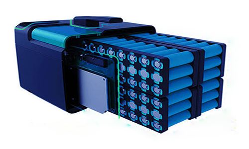
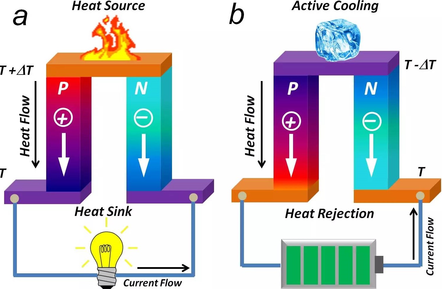
1. PresentationThe Multiphase Thermoelectric Converter is a direct thermal-to-electrical energy conversion system designed in order to ensure a net gain for the CrossFire Fusion Reactor by converting waste heat, from heavy electromagnetic losses(bremsstrahlung) in the reactor's core, efficiently into electricity. With which it is also possible to reduce weight and size of heat radiators [1] [2] making spacecraft more energy-efficient than ever. It is to be the most perfect combination: Electrodynamic Space Thrusters powered by Aneutronic Fusion Reactor with waste heat recovered by the Multiphase Thermoelectric Converter; forming a perfect/impeccable triad for providing a high degree of cleanliness and efficiency for space propulsion, practically, no thermal and radioactive waste.
The Multiphase Thermoelectric Converter consists of two opposing twisting electromagnetic forces, forming electrodynamic vortices, for axially and radially compressing a hot ionized gas F=q(v × B) forcing it to expand longitudinally transferring electrodynamically F=i(L × B) ε=(Bℓv sinθ) its energy to a multiphase electrical system to be effectively harvested by rectifiers. Wherein, the phase rotation keeps hot plasma centered far from electromagnetic coils, which allow to induce high pressure and withstand very high temperatures for virtually getting closer to the maximum efficiency η=1-(TC/TH), e.g. TC=300K, TH=30000K, η%=99%


Contents 1. Presentation 2. Background 3. Summary 4. Detailed Description 5. Operation and Calculation 6. Videos 7. Bibliography
2. BackgroundThe energy conversion from thermal energy directly into electrical energy is usually inefficient, typically ranges between 25% to 35% efficiency; for example, a typical gasoline generator operates at around 25% efficiency; in special cases, e.g. Combined Cycle Gas Turbines, may reach efficiencies over 50%. On the other hand, conversion from mechanical energy into electrical energy can be as high as 95% for large hydroelectric generators.
In accordance to the laws of thermodynamics, any efficiency cannot exceed or even reach 100% (work can be totally converted to heat energy, but heat cannot be completely converted to work), but do not prevent any efficiency from reaching or even exceeding 90%.
Higher pressures and temperatures can allow greater efficiencies η=1-(TC/TH), e.g. TC=300K, TH=3000K, η%=90%. However, temperatures are limited by ability of materials to withstand high temperature, which is not the case for magnetic fields that can withstand very high-temperature ions.
Heretofore, there have been known several devices designed for converting thermal energy into electrical energy:
 - Thermionic/thermoelectric converters (US patent: 3022430, 3194989, 3211586, 3273048, 3444400, 3430079, 3519854, 3702408, 3794527, 4014713, 4127804, 4303845, 4323808, 5459367, 5541464, 5780954, 5929372, 5942834, 5966939, 7129616, etc.);
- Magnetohydrodynamic (MHD) generators (US patent: 3122663, 3130330, 3182213, 3211932, 3294990, 3339092, 3414744, 3440458, 3478234, 3483405, 3487240, 3940641, etc.);
- Beta voltaic (US patent: 7663288, 7939986, etc.) and radioisotope thermoelectric (RTG) generators (US patent: 3615869, 3668015, 2006/0028144, etc.)All of them are still far from surpassing or even reaching 90% efficiency. Most of them remain below 30% efficiency.
Multistage depressed collectors (US patent: 3662212, 3925701, 3993925, 4096409, 6909235, 7368874, 7888873, etc.) can make TWTs more energy-efficient by recovering most of the energy remaining in the electron beam.
Prior devices that may be more closely related with this disclosure:
- Thermionic electric converter (US patent: 4303845) which is described as having a single helical coil, single-phase, self-oscillating;
- MHD [9] generators which use multiphase alternating currents for producing either (not both) moving (US patent: 3122663, 3440458, 3483405) or rotating (US patent: 3130330) magnetic fields;
- TWT multistage collectors (US patent: 7368874, 7888873) that are just designed to boost single-phase traveling waves on a sole coil, and their collectors that are just for recovering unused beam energy, not being aimed to deal with overvoltage and bidirectional flow of energy.Up to this time, there was no thermal-to-electrical converter designed for using multiphase alternating currents to produce both radial and longitudinal moving magnetic fields, resulting in opposing twisting forces, and also for using multistage collectors with multidirectional energy flow, in order of generating electricity from thermal energy in a more efficient way.
3. SummaryThe object of the present invention is to provide a workable method and apparatus to convert thermal energy electrodynamically into electrical energy with conversion efficiency twice or even thrice more than which is attainable by the prior art technologies, getting closer to the maximum efficiency.
The present invention provides an apparatus and method using a multiphase electrical system having multidirectional flow of energy, and electromagnetic transducers for generating opposing helically moving electromagnetic fields resulting in twisting forces, forming two contra-aligned electrodynamic vortices, for axially and radially compressing a hot ionized gas F=q(v × B) inducing it to expand longitudinally outwardly forcing F=i(L × B) and boosting electromotively ε=(Bℓv sinθ) the alternating electromagnetic fields of the transducers while escaping and squeezing out energy to the multiphase electrical system to be effectively harvested by a diode bridge and timely dispatched by IGBTs/MOSFETs to a battery bank.
Remaining residual heat energy is still recovered into electricity by using multistage ion beam collectors increasing even more the overall efficiency.


The electromagnetic transducers can be comprised either by concentric helix-coils, by inline stators or by electrodes axially and radially out-of-phase with each other.
Originated from radial and axial moving electromagnetic fields, the opposing twisting forces can produce and withstand higher pressure and temperature, which allow highly efficient levels of conversion η=1-(TC/TH) from any source of thermal energy, including coal, petroleum, burned gases, geothermal, biomass, solar, and nuclear, directly into electricity.
4. Detailed DescriptionIn the following will be described at least two different practical workable embodiments of this invention.
A preferred arrangement of electromagnetic transducers for generating helical moving force is shown in FIG. 1, comprised by six concentric solenoids (helix-coils) 1, 2, 3, 4, 5, and 6, axially rotated 60° from each other.
An alternative arrangement of transducers for generating helical moving force is shown in FIG. 2, comprised by six conventional stators 7, 8, 9, 10, 11, and 12, fed with electrical currents 60° out-of-phase with each other, wherein each stator is comprised by six conventional poles(windings) 13, 14, 15, 16, 17, and 18, also 60° out-of-phase with each other.
An electromagnetic transducer is any device that converts electric power (P=V*I) into alternating electromagnetic fields and vice versa; hence other alternative arrangements of transducers are possible, for example, it can be comprised by conventional electrodes (fed with voltages axially and radially out-of-phase with each other), or even capacitive plates, for primarily generating moving electric fields, secondarily resulting magnetic fields, for still producing helically moving electromagnetic fields.
A preferred embodiment for generating opposing twisting forces is shown in FIG. 3, comprised by the set of six concentric helix-coils already described in FIG. 1, more a mirrored (oppositely coiled) set of six concentric helix-coils 21, 22, 23, 24, 25, and 26, wherein each pair of opposing coils, e.g. 1 and 21, have a common terminal 19, and each downstream coil 21 are fed preferably with a voltage lower than its upstream pair 1, making the top side(upstream) a little stronger than the bottom side(downstream), unbalancing intake and exhaust pressures within its bore in order to make optional external devices for inwardly impelling hot gases, or other conductive fluids.
A continuation of the preferred embodiment of FIG. 3 is shown in FIG. 4, further illustrating an electron emitter 29, there are six electron emitters radially disposed around the embodiment midpoint for injecting preferably in-between the coils, and two optional magnets 27 and 28 with same magnetic polarity (NS SN) enclosing the coils for increasing the magnetic containment and also for forming magnetic cusp at the middle for injecting electrons, e.g: superconducting magnetic pressure (p=B2/2µ°) (8T ≈> 250 atm) (16T ≈> 1000 atm). Internally, the embodiment inner walls (chamber), including the coils, can optionally be coated with refractory and/or reflective material in order to minimize radioactively coupled heat transfer. The electron emitters can optionally be comprised of nichrome instead of tungsten due to its relatively high electrical resistivity and resistance to oxidation at high temperatures. The electron emitters can also be replaced by several types of negative ion sources such as electrospray, duoplasmatron, and so on. Also it can be replaced by positive ion sources; in this case, all polarities of power suppliers must conform to positively charged gases. More alternatively, electron emitters can be optional in case of already pre-ionized gases, or in case of coils fed by frequencies commonly used in plasma source/process, e.g. 13.56MHz [10]. However, in this disclosure, it will be explained a setup only using electron emitters, producing negatively charged gas, just to simplify further explanations.
A continuation of the embodiment of FIG. 4 is shown in FIG. 5 further illustrating a set of conventional multistage ion beam collectors 31, 32, 33, 34, 35, 36, and 37, a common wire 30, an electrical insulator 38 and a cover 39. The common wire 30 is at negative electric potential, or ground, and the common terminals 19 of the coils are at positive electric potential, forming a penning trap which helps to confine negatively charged gases.
A continuation of the preferred embodiment of FIG. 5 is shown in FIG. 6, further illustrating a casing 40 for adiabatically and hermetically sealing the apparatus.
A cross-section taken of FIG. 6 is shown in FIG. 7, showing its chamber interior wherein ionized gas is compressed by moving EM fields from the coils; and also clarifying the assembly of the set of ion beam collectors 31, 32, 33, 34, 35, 36, and 37, and their respective electrical insulators 41, 42, 43, 44, 45 and 46, evenly spaced and coaxially disposed along the outward axis. The electrical insulators can be preferably made of boron nitride due to its excellent thermal properties and a dielectric strength (6MV/m).
An embodiment for a heat engine system, using the preferred embodiment of FIG. 6, is shown in FIG. 8, further illustrating a heat source 48, a heat pipe 47, a pump 54, a heat sink 50, a valve 49, a cold pipe 55, a positive wire 57 for the common terminals 19 of the coils, six-phase wires 56 to feed the upstream coils, six-phase wires 60 to feed the downstream coils, a three-phase electrical transformer 53, a battery bank 51, a main power supply 52, secondary power suppliers 59, there are seven connected in series forming a pile, each having its respective negative terminal connected to its respective ion beam collector at left; the eighth power supply (from the bottom up) is for supplying the electron emitters via wire 58; the third power supply is connected via optical fiber to the eighth to control electron emissions, which will be further explained.
An embodiment for a combustion system, using the preferred embodiment of FIG. 6, is shown in FIG. 9, further illustrating a conventional air filter 61, a fuel intake 62, a conventional catalytic converter 63, and an exhaust pipe 64.
A schematic diagram of an electric circuit for a main control system is shown in FIG. 10, further illustrating a three-phase rectifier bridge comprised by six diodes D1, D2, D3, D4, D5, and D6, a three-phase inverter comprised by six IGBTs Q1, Q2, Q3, Q4, Q5, and Q6, three-phase pulse circuits P1, P2, and P3, phased 120° from each other, driving respectively gate circuit pairs G1/G2, G3/G4, GD5/GD6 for synchronously switching the IGBTs; the battery bank 51, a three-phase primary winding 69, a clock generator 75, and a main optical emitter 65 that will be further explained.
Alternatively, other switched-mode topologies, other semiconductor devices such as MOSFET, GTO, SCR, can be used instead of IGBT.
A schematic diagram of a control for electron emitter is shown in FIG. 11, further illustrating a three-phase center-tapped winding 71 for splitting three-phase into six-phase for feeding the coils, a three-phase rectifier bridge comprised by six diodes D13, D14, D15, D16, D17, and D18, a filament for the electron emitter 29, a current sense resistor R1, and an optical receiver 68 that will be further explained. The coils are fed by six-phase wires instead of three-phase, hence the secondary windings 71 (FIG. 11) are center-tapped to split three-phase into six phases, also the extra winding terminals are preferably to provide two voltages, higher voltage for the top coils (upstream) and lower voltage for the bottom coils (downstream) to force an outflowing direction for the downstream.
A schematic diagram of one of the secondary power suppliers is shown in FIG. 12, further illustrating a three-phase rectifier bridge comprised by six diodes D7, D8, D9, D10, D11, and D12, a three-phase inverter comprised by six IGBTs Q7, Q8, Q9, Q10, Q11, and Q12, three-phase pulse circuits P4, P5, and P6, phased 120° from each other, driving respectively gate circuit pairs G7/G8, G9/G10, GD11/GD12 for synchronously switching the IGBTs; a capacitor C1, a voltage divider comprised by R3 and R2, a positive terminal 72, a negative terminal 73 that is connected to ion beam collector, a three-phase secondary winding 70, a shunt resistor 74, an optical emitter 67 and an optical receiver 66 that will be further explained. Note: only one of the secondary power suppliers (the third) which is connected to collector 35 is that have the shunt resistor 74 and the optical emitter 67.
5. Operation and CalculationA basic operation for generating helical moving force can be better understood from the FIG. 1 wherein each coil 1, 2, 3, 4, 5, and 6, are fed with phase angles 60° apart, respectively 0°, 60°, 120°, 180°, 240°, and 300°, wherein the sequenced pattern of phase-shifted oscillations radially produce rotating magnetic fields similarly to a conventional rotating AC motor, and also longitudinally (or axially) produce moving magnetic fields similarly to a conventional linear AC motor, resulting in spiraling electromagnetic force with an electrodynamic vortex around and along its longitudinal axis creating an unidirectional drag force.
Another way of generating helical moving force can be better understood from the FIG. 2 wherein each conventional stator are 60° out-of-phase with each other and also each pole are 60° out-of-phase with each other, radially producing rotating magnetic fields and longitudinally producing moving magnetic fields, also resulting in helicoidal moving force forming electrodynamic vortex.
A basic operation for generating opposing twisting forces can be better understood from the FIG. 3 wherein each coil pair 1/21, 2/22, 3/23, 4/24, 5/25, and 6/26, are fed with phase angles 60° apart, respectively 0°, 60°, 120°, 180°, 240°, and 300°, thereby longitudinally producing opposing helicoidally moving electromagnetic fields, forming two electrodynamic vortices with their drag forces converging toward the common center. Note: they are oppositely coiled and fed with same phase sequence; alternatively, they can be coiled in the same direction and one side fed with opposite phase sequence for still generating two contra-aligned electrodynamic vortices.
Longitudinal and radial velocity of the moving force, for example:f=20kHz Longitudinal Radial vL=Lf vr=2πrf L=60cm r=20cm vL=12 *103 m/s vr=25.13 *103 m/s F=mv²/r ↔ F=m4π²rf² P=F/A (N/m² or J/m³) P=nRT/V
where L is the axial length of one turn, r is the radius, m is mass, v is velocity, V is volume, F is force, P is pressure, T is temperature, and f is frequency.It is preferable to use one pole per phase p=1 [0° 60° 120° 180° 240° 300°]. Another option is to use two pole per phase p=2 [0° 120° 240° 0° 120° 240°] which decreases radial and longitudinal velocities (vr=2πrf/p) (vL=Lf/p) and increases radial aperture/opening of the vortex which can be useful for very ionized gases facilitating escaping while electrodynamically transferring its energy to the system.
Before going on, succinctly here are some physics and technology foundations:
- It is widely known that: [7]- electric field changing in time generates a magnetic field and vice versa;
- electromagnetic fields interact with the matter;
- time-varying electromagnetic fields are produced by alternating currents and voltages;
- moving charges cause magnetic fields;
- magnetic fields exert forces on moving charges F=q(v × B);
- alternating or moving magnetic fields causes electrical currents on a wire F=i(L × B);
- flow rate of electric energy (P=E/t), or electric power P, is also is given by the product of applied voltage and electric current (P=V*I);
- electromotive force (EMF) refers to voltage generated by the force (ε=Bℓv sinθ) (measured in Volts and not Newtons) of time-varying magnetic fields, which can be used to induce an electric current to flow through a circuit in order to supply an electric power (P=V*I, P=V²/R, or P=I²*R) to a resistive load;
- electromagnetic transducers convert electric power into alternating electromagnetic fields and vice versa, e.g. antennas, electrodes, straight wires, coil wires, and so on.
- The fundamental concept behind Magnetohydrodynamics is that magnetic fields can induce currents in a moving conductive fluid (plasmas, liquid metals, and salt water or electrolytes), which in turn creates forces on the fluid and also changes the magnetic field itself.
- Magnetic refrigeration is a cooling technology based on the magnetocaloric effect [8], where magnetic fields induce the magnetic dipoles of the atoms and molecules of magnetocaloric materials to align, decreasing heat capacity by reducing radial vibrations, which forces an increasing on longitudinal vibrations, thereby cooling as they emit electromagnetic waves (thermal radiation), which represents a form of conversion of thermal energy into electromagnetic energy; however, this effect is insignificant on nonmagnetic materials, but on hot ionized plasmas, it can be meaningful enhancing even more the conversion efficiency, mainly if an internal coating is provided adiabatically in order to minimize the radioactively coupled heat transfer as aforesaid.
- It is interesting to cite the Vortex Tube (US patent: 1952281) that is a mechanical device, with no moving parts, that can produce simultaneously hot (outer vortex) and cold (inner vortex) air streams from an input stream at room temperature. It can optionally further help the reader to get an alternative envisage for understanding by comparisons of how an electrodynamic vortex enclosing an ionized gas vortex is able to receive energy.
- It is known from TWT’s technology that an energetic electron beam inside a helical coil push the alternating electromagnetic fields forwardly thereby boosting/amplifying the amplitude of single-phase electromagnetic waves while losing kinetic energy at each bunching cyclically/periodically induced by the alternating EM fields.
- Also it is known that for increasing potential stored energy in a charged capacitor is by doing work (τ=qU) of extracting electrons from its positive terminal and pushing them towards its negative terminal, increasing its voltage and consequently, increasing its stored energy (E=½CV²).Continuing, a basic operation of extracting thermal energy from a hot gas converting electrodynamically into electrical energy can be better understood from the FIG. 5 and FIG. 8 wherein inside the chamber interior, the incoming hot gas is (optionally as aforesaid) ionized by electron emitters 29, the opposing twisting forces produced by the coils (forming electrodynamic vortices) compress axially and radially the ionized gas F=q(v × B), and the ionized gas produces longitudinally an expansive outflowing force against the multiphase alternating fields electromotively boosting an opposing electrical current on the coil wires F=i(L × B), also voltage (ε=Bℓv sinθ), which is transferred back to the three-phase electrical transformer 53 (FIG. 8) producing an overvoltage on the primary windings 69 (FIG. 10) charging the battery bank 51 (FIG. 10) via the three-phase diode bridge rectifier. Wherein, the diode bridges effectively harvest energy, and the IGBTs synchronously dispatch energy.
Comparatively, at first glance, it works similarly to a Traveling Wave Amplifier (TWT), where amplitude of alternating electromagnetic fields is boosted while electrically charged particles pass through its interior, forcing the alternating fields outwardly thereby electromotively amplifying the amplitude of voltage and current (causing an opposing overflow of energy) on the coils while charged particles is losing kinetic energy; however, it amplifies multiphase standing waves instead of a single-phase traveling wave, and also it uses not only energy from electrons but also energy from electrically charged ions. Furthermore, the multiphase electromagnetic fields are amplified, and energy electromotively bounces back to the rectifier bridge which forms a diode clipping circuit for trimming off the overflow (boosts/peaks/spikes/surges) of energy that is transferred to be absorbed by the battery bank. By the way, even having some stationary wave on each coil, the coils are out-of-phase with each other, hence the overall effect due to sequential phase variation is still of generating axially and radially moving electromagnetic fields as previously described.
It is known that the ionization rate increases with an increase of the plasma temperature.[6]
Increasing velocity of moving fields or its magnetic flux, increases force F=q(v × B) increasing pressure and temperature improving thermal efficiency η= 1-(TC/TH). Opening possibility for ever higher conversion efficiency, e.g. TC=300K, (TH ≈> η%) (600K ≈> 50%) (3000K ≈> 90%) (30000K ≈> 99%)
Higher temperatures are possible because the rotating magnetic fields prevent high-temperature plasma from touching the chamber wall. The phase rotation keeps hot plasma centered inside the coils.
After escaping from the contra-aligned vortices produced by the coils, transferring most of its energy electrodynamically to the multiphase system, the outflowing negatively ionized plasma is electrostatically decelerated for gradually exchanging its remaining kinetic energy into potential energy landing smoothly on the multistage collectors (FIG. 7) losing its excess of electrons becoming neutral again. The electrons going from the collector towards negative terminal 73 (FIG. 12) causes overvoltage on capacitor C1, which is detected by the comparator, via the voltage divider R3 and R2, activating AND gates, enabling phased pulses to IGBTs which is switched transferring the potential energy stored in the capacitor to the three-phase secondary windings 70 (FIG. 12) causing overvoltage on the three-phase primary windings 69 (FIG. 10) charging the battery bank 51 (FIG. 10) via the three-phase diode bridge rectifier. In order to work properly, the electrons are emitted from the positive potential 58 so that useful work(τ=qU) be done by the ionized gas pushing the extracted electrons from the positive potential towards the negative potential, or ground, increasing potential energy stored in the capacitor (E=½CV²) as aforesaid.
Only one secondary power supply, connected to collector 35 (FIG. 7), sends its electrical current value, sensed by the resistor shunt 74, via the optical emitter 67 (FIG. 12) to the optical receiver 68 (FIG. 11) to be compared with half of current sensed by R1 to control the amount of electrons flowing from electron emitters 29 in order to control the amount of ionization. A general rule is that should be emitted at least a minimum current of electrons, e.g. 10 μA, and the current sensed by the shunt should be the half of overall current of electrons emitted in order to most of the negative ions to land far from the first collector 31 (FIG. 7) and a little closer to the last collector 37 that is the collector 35.
Due to the very high electrical potential differences, a control bus should be comprised preferably by optical fibers due to its high electrical insulation and immunity to electromagnetic interference.

The optical emitter 65 (FIG. 10) sends the timing signal, produced by the clock generator 75, to all secondary power suppliers via optical fibers to be received by their respective optical receivers 66, keeping the three-phase system perfectly synchronized for multidirectional flow of energy.
The apparatus for converting thermal energy directly into electricity without mechanical steam turbines can be better understood from the FIG. 8 wherein a heated gas from the heat source 48 flows to the already described preferred embodiment (FIG. 6) via the pipe 47. The preferred embodiment extracts maximum of energy possible from the heated gas transferring it to the battery bank 51. The remaining thermal energy that cannot be employed for conversion is dissipated to outside via the heat sink 50 by compressing the gas via the pump 54. The valve 49 controls flux of cold gas toward the heat source via the pipe 55 completing the thermal cycle.
The apparatus for extracting energy directly from fuel combustion can be better understood from the FIG. 9 wherein fuel is injected via the intake 62 to be mixed with air coming from the filter 61, towards to the already described preferred embodiment (FIG. 6), wherein inside the chamber, the twisting forces pressurize, and the six electron emitters 29 helps to ignite the air/fuel mixture, the multiphase coils and the multistage collectors convert thermal energy into electricity as previously explained. The unbalanced voltage between top and bottom coils impels byproducts of combustion downward to the exhaust pipe 64 passing through the catalytic converter 63 to reduce its toxicity.
Currently, in the worldwide, approximately more than two-thirds of all the energy produced by burning fuels or generated in thermal power plants is lost in the form of waste heat; and with this invention, it is possible to recover most of that wasted energy, reducing worldwide pollution. Also with this invention, the waste heat from electromagnetic losses (bremsstrahlung) in the aneutronic fusion reactor core can be turned efficiently into electricity, assuring the overall efficiency stay well above the breakeven point assuring a net gain for the aneutronic fusion reactor(MAGNETIC AND ELECTROSTATIC NUCLEAR FUSION REACTOR); perfect combination, virtually, no thermal and radioactive waste, a dense energy source with an extremely high degree of cleanness and efficiency to supply the world's future energy needs.
In this way, the electrodynamic thermoelectric converter in this disclosure can improve conversion efficiency from any sources of thermal energy such as coal, petroleum, natural gas, hydrogen, geothermal, biomass, biofuel, solar, and nuclear, directly into usable electricity, useful for increasing the efficiency of existing thermal power plants. And also can be an important breakthrough for electric vehicles to recharge battery packs and to power electric motors, reducing automotive waste heat, fuel consumption and carbon emission, providing a huge improvement in fuel efficiency, making it more environmentally friendly.
6. Videos
See also:
Phase-shifted Electrodynamic Propulsion - Video
7. Bibliography- Atomic Rockets Basic Design (Retrieved 2011-09-27) "Heat Radiators 1"
- Atomic Rockets Real Designs (Retrieved 2011-09-27) "Heat Radiators 2"
- DR Brown et al. (March 2010) "Alternatives to Vapor Compression Technology for Space Cooling"
- Phase-shifted Electrodynamic Propulsion - Video (2010-11-28)
- “Douglas” M. Ferreira Palte (July 08, 2011) "Phase-shift Plasma Turbine - Brief Presentation"
- Plasma Basics (Retrieved 2011-10-18)
- Fundamentals of Electricity (Retrieved 2011-10-18)
- Benjamin Podmiljšak (Retrieved 2011-10-18) The magnetocaloric effect
- CERN (Feb. 23, 2005) Superconducting Magnets For Space Application Nuclear Power and Propulsion Systems
- Maher I. Boulos (1985) "The inductively coupled R.F. (radio frequency) plasma"
- “Douglas” M. Ferreira Palte (Jan 03, 2012) "Multiphase Thermoelectric Converter - Brief Presentation - v1"
- “Douglas” M. Ferreira Palte (Out 29, 2013) "Multiphase Thermoelectric Converter - Brief Presentation - v2"
Share Http URL: http://www.wittx.cn/get_news_message.do?new_id=1002

Best Last Month
Information industry by wittx

Information industry by wittx

Information industry by wittx
Information industry by wittx
Information industry by wittx

Information industry by show
Information industry by wittxNature High-efficiency solar thermoelectric conversion enabled by movable charging of molten salts
Information industry by wittx

Computer software and hardware by wittx
Information industry by wittx
